Difference between revisions of "Qbcan compact"
(→qbcan mechanical interfaces) |
(→qbcan mechanical interfaces) |
||
| Line 52: | Line 52: | ||
qbcan compact has been designed mostly with two configurations in mind: | qbcan compact has been designed mostly with two configurations in mind: | ||
| − | * Central interface: | + | * Central interface: Hole at the centre of the board that enables to wrap components around a central pillar in the CanSat, giving easy accessibility to the external faces. |
| − | * Three peripheral interfaces: This solution is more robust but the three pillars reduce the accessibility of payloads to the external faces. | + | * Three peripheral interfaces: three holes at the edge of the board. This solution is more robust but the three pillars reduce the accessibility of payloads to the external faces. |
The board has four holes suitable for rods/bars/fasteners up to 3mm in diameter. It is recommended to secure the qbcan board in a way that the mechanical constraints do not impart unequal forces along the board, trying to twist it or bend it, as this could cause failure of some of the solder joints or components. | The board has four holes suitable for rods/bars/fasteners up to 3mm in diameter. It is recommended to secure the qbcan board in a way that the mechanical constraints do not impart unequal forces along the board, trying to twist it or bend it, as this could cause failure of some of the solder joints or components. | ||
Revision as of 18:05, 5 October 2016

This document is the qbcan compact user manual. It describes the qbcan compact CanSat kit and the software setup. It provides a step-by-step guide to help the user go through the development process, from the opening of the qbcan kit to transmitting data from one qbcan to another.
The qbcan kit has been developed by Open Cosmos for the users that want to have a working solution out of the box avoiding the assembly of the parts and soldering and hence focus the efforst on the payload. Open Cosmos is a start-up willing to use nano-satellites to provide simple and affordable access to space to organisations ranging from SMEs and research institutions to space agencies in developing countries.
Open Cosmos is based in London with an international mindset and the ambitious purpose to bring the possibility to use and develop space technology to a wider public. With that in mind, Open Cosmos has developed the qbcan, an educational CanSat kit for primary, secondary and tertiary education. The qbcan aims to engage and motivate the next generation of space engineers and scientists.
Support
In case you have any problem during the assembly or operations please post your questions into the Open Cosmos community so all the users can benefit from the content.
Sensors terminology
| BMP180 | Pressure and temperature sensor |
|---|---|
| LLC | Low Level Converter |
| RFM69 | 433 MHz transceiver |
Contents
System description
The qbcan bus provides all the required capabilities of a standard CanSat mission: radio communications, a temperature and pressure sensor and a computing platform with a wide range of interfaces. The user can then add extra functionalities (adding sensors and actuators via the provided interfaces) and develop more complex systems.
The main components of the qbcan are:
- Arduino Pro Micro compatible microcontroller.
- RFM69HW 433MHz transceiver.
- BMP180 pressure and temperature sensor.
- Low Level Converter.
- Antenna/Yagi antenna connector.
- Printed circuit board (PCB) that integrates the previous components.
- Rapid-development software library that interfaces with the transceiver and the pressure and temperature sensor.
- 9V battery (not included).
The qbcan modular is the smallest qbcan kit with all the components integrated into the same board. This enables the users to maximise payload volume and mass and to be mounted in most convenient section of the CanSat main body. The 0.1 inch header allows easy
The qbcan is compatible with the Arduino programming interface which is open-source and users are encouraged to share their creations and distribute their work with the Open Cosmos community.
qbcan mechanical interfaces
qbcan compact has been designed mostly with two configurations in mind:
- Central interface: Hole at the centre of the board that enables to wrap components around a central pillar in the CanSat, giving easy accessibility to the external faces.
- Three peripheral interfaces: three holes at the edge of the board. This solution is more robust but the three pillars reduce the accessibility of payloads to the external faces.
The board has four holes suitable for rods/bars/fasteners up to 3mm in diameter. It is recommended to secure the qbcan board in a way that the mechanical constraints do not impart unequal forces along the board, trying to twist it or bend it, as this could cause failure of some of the solder joints or components. It is also recommended not to load the board supporting any external components, for example batteries or other electronics, part from the specified four loading points. Other components should have their own mechanical support in order to avoid damaging qbcan.
A CAD step file has been produced in order to aid the development of structures and accessories for the qbcan compact. Please keep 3 mm at least from the top layer and bottom layer of the boards to clear components in them.
qbcan electrical interfaces
The qbcan compact contains a wide range of interfaces:
- Micro-USB connector programming interface
- Monopole 433 MHz antenna on qbcan option
- SMA female connector for external antenna on qbcan GS option
- 32 pin 0.1 inch (2.54mm) header:
- 6 analogue inputs with 10-bit ADCS
- 14 Digital I/O pins
- 3 PWM output pins
- 5V and 3.3V power outputs
- 5- 12V power input
- I2C, SPI, UART serial communication ports
The pinout of the qbcan compact 32 pin header can be seen in table and figure below (pin numbers are printed in qbcan PCB):
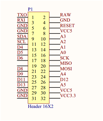
| Pin number | Function | Comment | Pin number | Function | Comment |
|---|---|---|---|---|---|
| 1 | TXO | UART transmit line | 2 | RAW | 5V min 12 V max power input |
| 3 | RXI | UART receive line | 4 | GND | Ground |
| 5 | GND | Ground | 6 | RESET | Reset pin, connect to ground to reset qbcan microcontroller |
| 7 | GND | Ground | 8 | VCC5 | 5V regulated power output |
| 9 | SDA | I2C data | 10 | A3 | Analog input pin or digital I/O pin |
| 11 | SCL | I2C clock | 12 | A2 | Analog input pin or digital I/O pin |
| 13 | D4 | Digital I/O pin | 14 | A1 | Analog input pin or digital I/O pin |
| 15 | D5 | PWM or digital I/O pin | 16 | A0 | Analog input pin or digital I/O pin |
| 17 | D6 | PWM or digital I/O pin | 18 | SCK | SPI clock |
| 19 | No functionality | 20 | MISO | SPI master input | |
| 21 | D8 | Digital I/O pin | 22 | MOSI | SPI master output |
| 23 | D9 | PWM or digital I/O pin | 24 | A4 | Analog input pin or digital I/O pin |
| 25 | D11 | Digital I/O pin | 26 | D12 | Digital I/O pin |
| 27 | D13 | Digital I/O pin | 28 | A5 | Analog input pin or digital I/O pin |
| 29 | GND | Ground | 30 | VCC5 | 5V regulated power output |
| 31 | GND | Ground | 32 | VCC3.3 | 3.3V regulated power output |
The I2C interfaces are shared with the pressure and temperature sensors, but are also available to the user.
Microcontroller
The core of the qbcan is an ATmega32U4 running at 5V/16MH. The microcontroller provides the required computing power to the CanSat and is easy to program using the Arduino integrated development environment.
Transceiver
A RFM69HW 433 MHz transceiver is included to provide long range communication capabilities to the qbcan. The main features of the transceiver are:
- +20 dBm - 100 mW power output capability.
- High sensitivity: down to -120 dBm at 1.2 kbps.
- Programmable output power: -18 to +20 dBm in 1 dB steps.
- Fully integrated synthesiser with a resolution of 61 Hz.
- Frequency selectable by software over 256 different channels.
- 255 possible nodes in every channel.
- FSK, GFSK, MSK, GMSK and OOK modulations.
- Hardware 128 bit AES encryption.
- Over 400+ meters range using whip antennas and several km range using a Yagi antenna on the receiving end.
The transceiver software, included with the qbcan, is interrupt driven (asynchronous response to incoming communications). The antenna of the qbcan compact acting as Cansat is a simple quarter wavelength monopole antenna. The qbcan compact ground station version includes a SMA adaptor in order to connect Yagi antennas in order to improve range and quality of the radio link. Using this transceiver, a qbcan can be used in a CanSat while another qbcan is used as ground station, receiving telemetry from the CanSat (and sending it to a PC via the USB port) and sending commands to the CanSat.
Temperature and pressure control
The qbcan includes a BMP180 barometric pressure and temperature sensor. This sensor communicates over I2C and provides:
- Pressure sensing range: 300-1100 hPa (9000m to -500m above and below sea level).
- Up to 0.02 hPa / 0.17m altitude resolution.
- -40 to +85°C operational range, +-2°C temperature accuracy.
Power
The qbcan can be powered by a standard 9V battery (not included) or a power supply from 5V to 12V. The user has the following power buses available from qbcan compact:
- 5V regulated power
- 3.3V regulated power
qbcan compact can supply a total max 500 mA from all regulated buses (current from 5V + current from 3.3V <= 500mA). If more than a total of 500 mA are planned to be used (adding the 5V and 3.3V buses) it is recommended to use the raw battery voltage with its dedicated voltage regulator.
Library
A qbcan software library is included. It provides an easy-to-use interface with the transceiver and pressure and temperature sensors. An example code is provided to speed up the development of the CanSat mission. The library includes a CanSat example and a ground station example.
Getting started
In order to develop software for the Arduino Pro Micro and use the provided qbcan library, the development computer needs to be properly configured.
The following page: qbcan software installation provides a step by step guide to set up the development environment.
In order to complete the software installation, one qbcan is required.
Powering qbcan up
qbcan compact can be powered via USB, 5V-12V power IN or both at the same time. Once power is provided, qbcan compact will start running the software on board automatically.